xpsac5121p wiring diagram
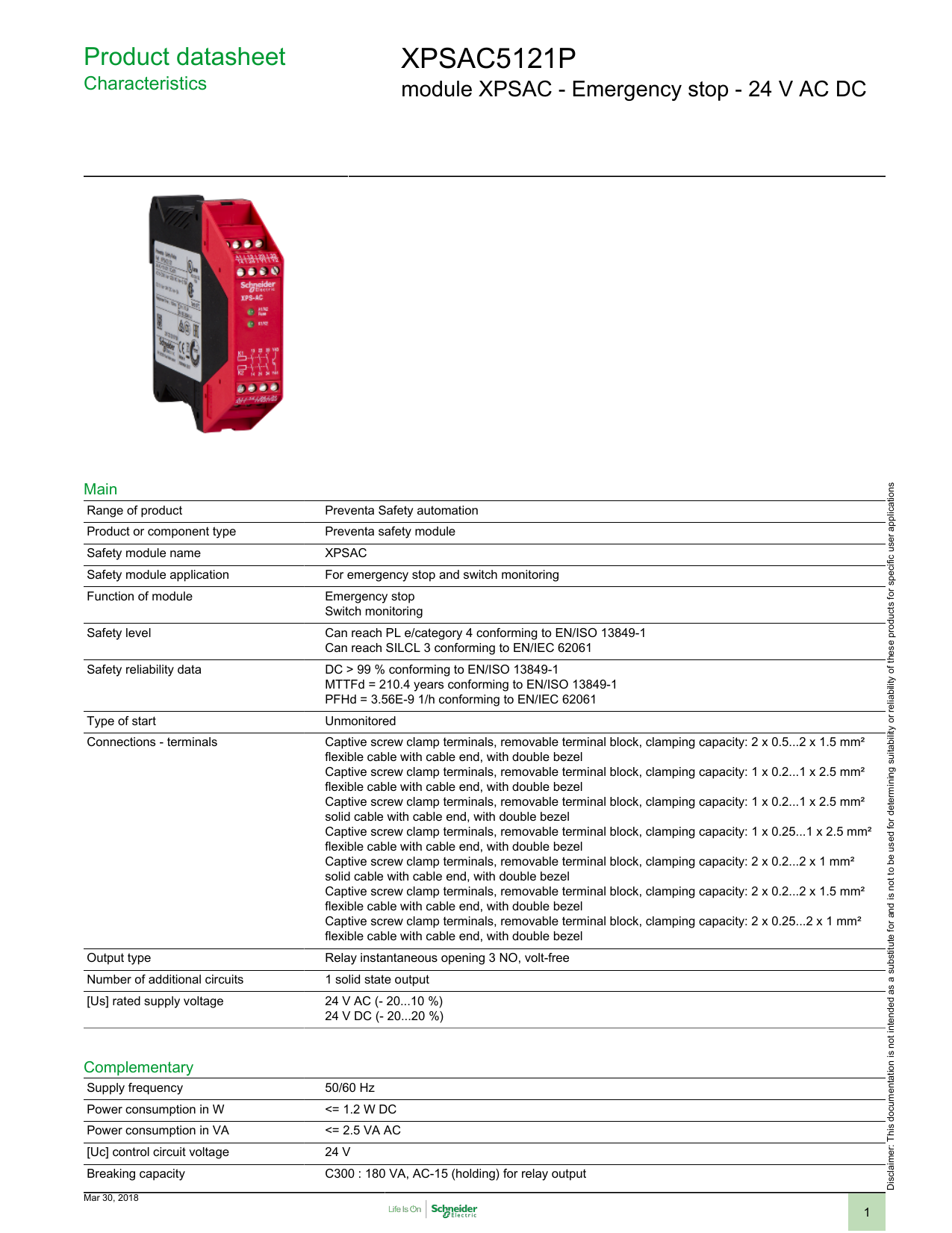
XPSAC5121P - module XPSAC - Emergency stop - 24 V AC DC. 180 VA AC-15 holding relay output.
Xpsac5121p Schneider Electric Manualzz
WIRING DIAGRAM FOR MODULE XPS-AF SAFETY RELAY.
. Note There are no user serviceable components in the module. 2 Complementary Supply frequency 5060 Hz Power consumption in W. XPSAC5121P Main Range of product Preventa Safety automation.
Radwell provides a 2-year warranty on every item we sell and repair. 0503 2003 Schneider Electric All Rights Reserved 03 Emergency stop Emergency stop. XPSAC5121P PDF - Documentation language en.
1 Click on Download. 392017 103921 AM. 1 Click on Download Documents.
3 3. 2 Click on Instruction sheet. Wiring diagrams Guard monitoring with 2 safety limit switches Category 4 conforming to standard EN 954- Wiring diagram 230 Logic GND ESC external start conditions EDM external devices monitoring 1 Technical characteristics for maximum rating of fuses see page 2122.
For maximum protection of the outputs please refer to TECHNICAL DATA. Wiring Diagrams Refer to the Instruction Sheet To download the instruction sheet follow below procedure. Wiring Diagrams Refer to the Instruction Sheet To download the instruction sheet follow below procedure.
3 3. 2 Click on Instruction sheet. XPSAC5121 Datasheet module XPSAC - Emergency stop - 24 V ACDC - List of Unclassifed Manufacturers.
Wiring Diagrams Refer to the Instruction Sheet To download the instruction sheet follow below procedure. Radwells 2 Year Warranty. 1 Click on Download Documents.
100 MS RESPONSE TIME. Wiring Diagram Book Download Schneider Electric Online Wiring Electrical Wiring Diagram Books Eyelash Me Renf22r2mmw Schneider Electric Nfc Time Delay Relay Screw 0 1 Sistema Example One Schneider Electric Sistema Example 1 June Schneider Electric Legacy Relays 782xbxc 24a Relay General Schneider Electric Wiring Diagrams Chupanhkyyeudep Net. Our free 2-year warranty makes every Radwell purchase a dependable reliable investment in your companys future.
2 Only applicable to XPSMC32Zp Presentation. For Emergency stop and switch monitoring. Size 007 MB.
Wiring Diagrams Refer to the Instruction Sheet To download the instruction sheet follow below procedure. 2 Uimp rated impulse withstand voltage 4 KV III IEC 60947-5-1 4 kV III DIN VDE 0110 part 1 Local signalling 2 LEDs Current consumption 40 mA 24 V DC on power supply. XPSAC5121P PDF - Documentation language en.
2 Click on Instruction sheet. Synchronisation time between inputs Unlimited Unlimited 75 ms automatic start Unlimited or 15 s depending on wiring Unlimited Input channel voltage 24 V48 V version a and 24 V c 48 V a 24 V c 24 V c 24 V c 24 V c 24 V48 V or 110 V120 V230 V version 115 V a 230 V 48 V a 48 V Module type XPSAC XPSAXE XPSATE XPSAV XPSABV Pages 8 8. 1 Click on Download Documents.
Size 3436 MB pdf. For safety circuits according to EN 60204-11992EN418 safety devices must use only the hard contacts outputs between terminals 13-14 23-24 and 33- 34. Are used for monitoring Emergency stop circuits conforming to standards EN ISO 13850 and ENIEC 60204-1 and also meet the safety.
Request SQUARE D XPSAC5121. SAFETY RELAY 300V 25A PREVENTA online from Elcodis view and download XPSAC5121 pdf datasheet More Switches Relays specifications. Wiring diagram and Functional Diagram are available on the web via the partnumber.
1232013 50823 AM. Catalogue Retriever Servlet Created Date. 2 Click on Instruction sheet.
Shemeck Pl
Shemeck Pl
Shemeck Pl
Shemeck Pl